SERIES AND PARALLEL CIRCUITS SIMULATION
LAB
Unit Overview
In the previous unit you
learned all about electricity. You built your knowledge and understanding of
circuits, voltage, current, resistance, and more. This unit is a lab-based task
to demonstrate what you learned about electricity and circuits in a practical
manner.
Task
You will build a variety
of circuits in this activity in order to analyze how they work. For each
scenario, follow the building instructions carefully in order to obtain the
desired outcomes. Print out the Students Response document to record your
answers. Student Response Document
Directions
Go to the following
website:
https://phet.colorado.edu/en/simulation/circuit-construction-kit-dc
You now have the raw material to create a circuit.
Take a moment to look over the screen and find all the different materials. To
build a circuit you will need several wires, a light bulb, a voltage source, a
voltmeter, and a non-contact ammeter. Play around with it to learn how to grab
and manipulate these tools. Once you are comfortable, click “Reset All” and
move on to the scenarios.
Scenario 1: Simple Series Circuit
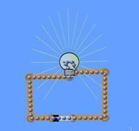
Build a simple series circuit that consists of 6
pieces of wire, 1 light bulb, and 1 battery (voltage source). In order to
complete the circuit, the red circles at the end of each must overlap. Please
note that the light bulb also has TWO circles. Your circuit is complete and
working when the light comes on and the blue dots begin moving.
1. Include a screenshot of your circuit here.
Example:

2. What do the blue dots represent, and how do you
know?
3. Place the voltmeter near the battery. Align the red
lead to one end of the battery and the black lead to the other end. What is the
voltage?
4. Place the ammeter crosshairs over the moving blue
dots. What is the reading?
5. Right-click on the battery to alter the voltage and
internal resistance of the battery. Make observations on how this changes the
readings on the voltmeter and ammeter. Record your observations below.
6. Under Advanced, click “Show” and alter the resistivity
of the wire. Record your observations. Click “Reset All” then move on to the
next scenario.
Scenario 2: Series Circuit with
Multiple Resistors
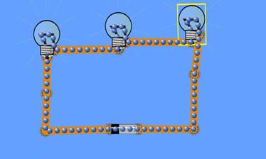
Build a series circuit with one battery, 3 lightbulbs,
and 8 wires. Be sure to place the lightbulbs in a series and not parallel with
one another.
1. Include a screenshot of your circuit here.
(Example:

2. Use the voltmeter on the battery. What is the
voltage?
3. Use the non-contact ammeter over a wire. What is
the amperage?
5. Right-click on the battery to alter the voltage and
internal resistance values. Describe what happens when those values are
changed.
Scenario 3: Parallel Circuit
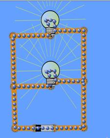
Parallel circuits provide more than one path for
electrons to move. Construct a parallel circuit that contains 10 wires, 2 light
bulbs, and 1 battery. The blue dots will be moving and both light bulbs will be
on once your circuit is complete.
1. Include
a screenshot of your circuit here.
(Example:

2. Use the voltmeter and non-contact ammeter to
measure electron flow and push.
3. What is the voltage?
4. What is the amperage? Check it close to the battery
as well as close to the light bulbs.
5. How do these values compare with those of Scenario
1? Does this surprise you? Why or why not?
6. Now right click on one of the wires connected to a
light bulb. Remove the wire and record your observations.
7. Does this affect the voltage, amperes, or visually
change the appearance of the light bulb?
8. Replace the wire. Now remove one of the wires
touching the voltage source. What happened?
Scenario 4: Create Your Own Circuit
1. Create
a functioning circuit using materials of your choice. Include a screenshot of
your circuit here.
2. Is your circuit in series or parallel? Explain.
3. What is the voltage and amperage of your circuit?
How does it compare to the circuits in Scenarios 1-3?
4. Manipulate the voltage and resistance of the
battery, and explain what happens in your circuit.
Review Questions
You may need to re-build a series circuit and a
parallel circuit in order to answer these questions.
1. As the number of resistors (light bulbs) increases,
what happens to the overall current within a series circuit and a parallel
circuit?
2. As the number of resistors (light bulbs) increases,
what happens to the overall resistance within a series circuit and a parallel
circuit?
3. If one of the resistors is turned off (i.e., a
light bulb goes out), what happens to the other resistors in a series circuit
and a parallel circuit?
Unit Submission
When you are finished with the simulation lab, upload
your response sheet and type “Complete” for question #1.
 Now answer question 1.
Optional Extension – Hands-On Lab
Print the two handouts, titled “Circuit Logic”
and “I
See the Light.”
Gather your supplies: a 2-AA battery holder, two AA
batteries, three pieces of insulated wire (each about 30cm or 12” long) with
alligator clips on each end, a lightbulb holder with screw terminals, a
lightbulb, a manila folder, scissors, aluminum foil, masking tape, and a hole
punch.

Before beginning the lab, read “Circuit Logic” and
complete Part I of “I See the Light.”
Complete Part II of the worksheet and build the
Immediate Feedback Quiz (IFQ).
There are parts of the lab that reference interactions
with your classmates. You can alternately complete this with other people in
your home, friends, neighbors, etc. or just do it on your own to make sure your
IFQ works properly.
Complete Part III of the worksheet.